Ramps 1.4 is open hardware: you can redistribute it and/or modify it under the terms of the GNU General Public License as published by the Free Software Foundation.
Disclaimer:The instructions below provide a proven working way to assemble the 3D printer controller. You may go an alternative route but please make sure you understand what you are doing. Reversing input power and/or inserting stepper drivers incorrectly will destroy the electronics and cause a serious fire hazard. Such misuse of ZYLtech boards is not covered by the warranty.
|
Important things to consider before you begin
CH340 Driver Though the CH340 Mega 2560 board is usually installed automatically when connected to your computer, manual installation is sometimes required. Please follow steps 4 and 5 on our Trouble Shooting page. There are also many online resources regarding the CH340 driver on various operating systems; a simple google search is a good place to start. Contact us if you need further assistance. |
Marlin firmware configuration
|
Please note: this configuration is for version 1.1.x |
If your board number is different, you need to check boards.h to select the right board. |
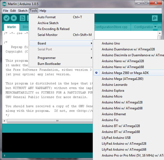
Firmware upload(See Figure 4)
|
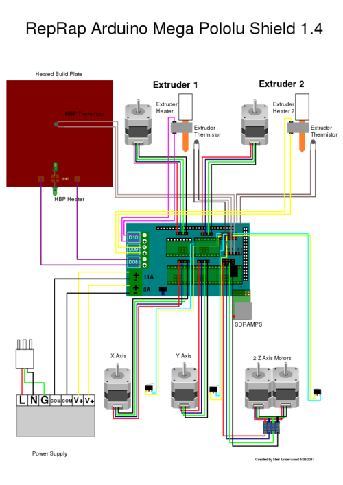
Hardware assembly and test
- Disconnect USB cable.
- Mount the RAMPS 1.4 Board onto the Mega 2560 board. The headers and pins on each board may need some adjustments to align properly. If it doesn't fit, don't force it! You may damage the headers or pins.
- Mount all a4988 or DRV8825 drivers making sure the EN PIN is aligned with EN header, otherwise you may damage the driver or Mega 2560 board.
- Connect the thermistors to T0 or T1. If everything is correct, you should be able to read temperature from printrun.
- Further tests may be done even without heat bed or extruder connected. Connect 12V power and double check the polarity. Set the heatbed and extruder temperatures to 110 and 230 °C, respectively. Two LEDs on the RAMPS board will be turned on indicating the power outputs are working. Then turn off the heat bed and extruder power.
- Send command M106 S255 and another LED will be turned on indicating fan is working. Then send M107 to turn it off.
Smart Controller installation
If your kit came with a LCD smart controller, the hardware installation process is fairly simple. Connect AUX, EXP1, EXP2 to RAMPS via the supplied adapter and ribbon cable. Every smart controller is tested before shipping. In the event yours is not working, please reset the smart controller and double check the connection. You may need to swap the ribbon cables.
12864 full graphic smart controller requires an additional lib: U8glibPlease unzip and copy to your Arduino library folder. You also need to configure Marlin firmware. First, uncomment line 559 in marlin 1.0.0 or line 570 in 1.0.2 in configuration.h
|
Then, change the rotary encoder direction in Pins.h, line 772 |
The firmware configured for the 12864 smart controller that sold by ZYLtech can be downloaded here.
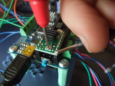
Adjusting current limit (reference voltage) for stepper driverA4988 sold by Zyltech, Rs=0.1 ohm. Thus the max current is Vref/0.8. Drv 8825 sold by ZYLtech. Max current = Vref x 2 For a starting point, you may set the max current to 1A. If the motor over heats, reduce the Vref. If the motor does not move or miss-steps, increase the Vref. |


