First Run
Important things to consider before you begin:
1) Double check the power input polarity (“+” and “-“)
2) Be aware of the orientation of stepper drivers. Please note the potentiometer (pot) on A4988 and DRV8825 are at the opposite side

Pre-flight Checklist
1. Do a visual check of all soldered points on the new board
2. Plug the shield into an Arduino board and load the GRBL Firmware following the steps bellow:
- Download the GRBL source code. Download here
- Unzip the download and you’ll have a folder called "grbl-master"
- Launch the Arduino IDE. (Please make sure you are using the most recent version of the Arduino IDE.)
- Load GRBL into the Arduino IDE as a Library. (Click the "Sketch" drop-down menu, then navigate to "Include Library", and select "Add .ZIP Library")
- IMPORTANT: Select the "Grbl" folder inside the "grbl-master" folder, which only contains the source files and an example directory. (If you accidently select the .zip file or the wrong folder, you will need to navigate to your Arduino library, delete the mistake, and re-do this step.)
- Open the "GrblUpload" Arduino example. (Click the "file" down-down menu, navigate to "Examples->Grbl", and select "GrblUpload")
- Compile and upload GRBL to your Arduino. (1. Connect your Arduino Uno to your computer. 2. Make sure your board is set to the Arduino Uno in the "Tool->Board" menu and the serial port is selected correctly in "Tool->Serial Port". 3. Click the "Upload" and GRBL should compile and flash to your Arduino! Note: flashing with a programmer also works by using the "Upload Using Programmer" menu command.)
3. Open up a serial connection to the Arduino board and check if GRBL is running. (We use Universal G-code sender to connect to GRBL)
4. A4988 stepper drivers need adjustment for reference voltage. We will cover that in detail later.
5. Testing each stepper controller socket individually is critical.
- Make sure the external high voltage power is not powered-up or connected
- Connect a stepper motor to the stepper controller socket you want to test. This is very important because the Pololu Stepper drivers are designed to ramp up the current until it reaches the needed current to run. Without a stepper motor connected there will be nothing to consume the current and you can end up damaging the stepper driver if it over-heats in the process.
- Next, install the stepper motor driver ensuring that the enable pin on the driver aligns with the enable pin on the shield.
- Connect the external power to the shield, making sure you connect the power up the right way. If not connected correctly you can cause damage to the shield, stepper motor drivers and Arduino board.
- Send a g-Code to the Axis you are testing. The stepper motor should move if everything is working. (GCode Example : “G1 X5? or “G1 X0? or “G1 Y5?)
- Repeat the above process with each axis using the same stepper driver.(Testing with one driver reduces the risk of damaging multiple stepper drivers at the same time.)
6. After all the above have been checked connect all the drivers and power up the system.
Current Limit (Reference Voltage) Adjustment for Stepper Driver
A4988 sold by Zyltech, Rs=0.1 ohm. Thus the max current is Vref/0.4
Vref (Reference Voltage) is measured using a multimeter at the points shown

Drv 8825 sold by Zyltech. Max current = Vref x 2
Reference voltage is adjusted with a small screwdriver at the point indicated with the white arrow in the picture to the right. We suggest adjusting the reference voltage in small increments - no more than a quarter turn at a time. For a starting point, you may set the max current to 1A. If the motor over heats, reduce the Vref. If the motor does not move or miss steps, increase the Vref.
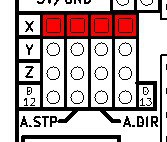
Jumper Settings
Jumpers are used to configure the 4th Axis, Micro stepping and endstop configuration.
4th Axis Configuration
Using two jumpers the 4th axis can be configured to clone the X or Y or Z axis. It can also run as an individual axis by using Digital Pin 12 for Stepping signal and Digital Pin 13 as direction signal. (GRBL only supports 3 axis’s at the moment)
|
|
|
|
|


Configuring Micro Stepping for Each Axis

Pololu A4988 Stepper Driver configuration:
MS0 MS1 MS2 Microstep Resolution
Low Low Low Full step
High Low Low Half step
Low High Low Quarter step
High High Low Eighth step
High High High Sixteenth step
Pololu DRV8825 Stepper Driver configuration:
MODE0 MODE1 MODE2 Microstep Resolution
Low Low Low Full step
High Low Low Half step
Low High Low 1/4 step
High High Low 1/8 step
Low Low High 1/16 step
High Low High 1/32 step
Low High High 1/32 step
High High High 1/32 step
 By default GRBL is configured to trigger an alert if an end-stop goes low (becomes grounded.) This has been debated and some people have requested to have active high end-stops. The jumpers in the picture above provide options for both. The left image indicates the connection required to run with the default GRBL setting. (This Jumper was only introduced in Version 3.02)
|
 End-stop switches are standard “always open” switches. An end-stop is activated when the end-stop pin connects to ground (when setup with default GRBL settings.)
|
End Stop Configuration
The end stop switches that come with the ZYLtech kit have three wires. Such end stops are easy to use, monitor and install, especially compared to the bare mechanical switches. However, the CNC shield only provides 2 PIN headers in contrast to the RAMPS shield. There are two ways to install the end stops:


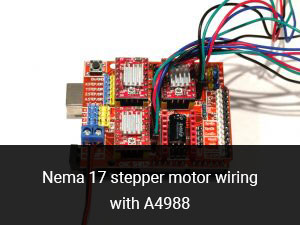
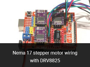
Wiring of Motors
Wiring ZYLtech Nema 17 stepper motors is simple. Plug in the connectors to the headers for each axis. If a motor turns the incorrect direction, simply rotate the plug 180 degrees.